What Is a COB Character LCD and How Does It Work?
A COB Character LCD is a compact text display built for clear, low-power information output. COB means “Chip on Board,” describing how the controller chip is mounted directly onto the circuit board. This construction removes the need for a separate packaged driver, saving space and reducing assembly costs. The display usually contains fixed character cells, such as letters, numbers, and symbols. A controller activates selected segments through electrical signals. The liquid-crystal layer then changes how light passes through each segment. It does not produce light by itself.
In practical equipment, a COB Character LCD may show temperature, operating modes, battery status, or simple instructions. Its familiar green, gray, or blue screen can appear in meters, industrial controllers, appliances, and handheld instruments. The display connects through parallel or serial interfaces, depending on its controller design. Engineers must check voltage, pin assignments, viewing direction, operating temperature, and backlight requirements before selecting a module. Small differences matter.
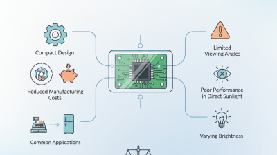
A simple explanation is useful, but incomplete. Contrast can fall in cold environments. Strong sunlight may require a reflective design. Backlight brightness also affects power consumption. The epoxy-covered chip may look simple, yet repair becomes difficult if the bonded circuit fails. Some product descriptions use “COB” loosely, so reliable specifications should confirm the internal construction. This article examines how the module is assembled, how its pixels respond, and why its practical performance sometimes differs from expectations. That gap deserves attention.
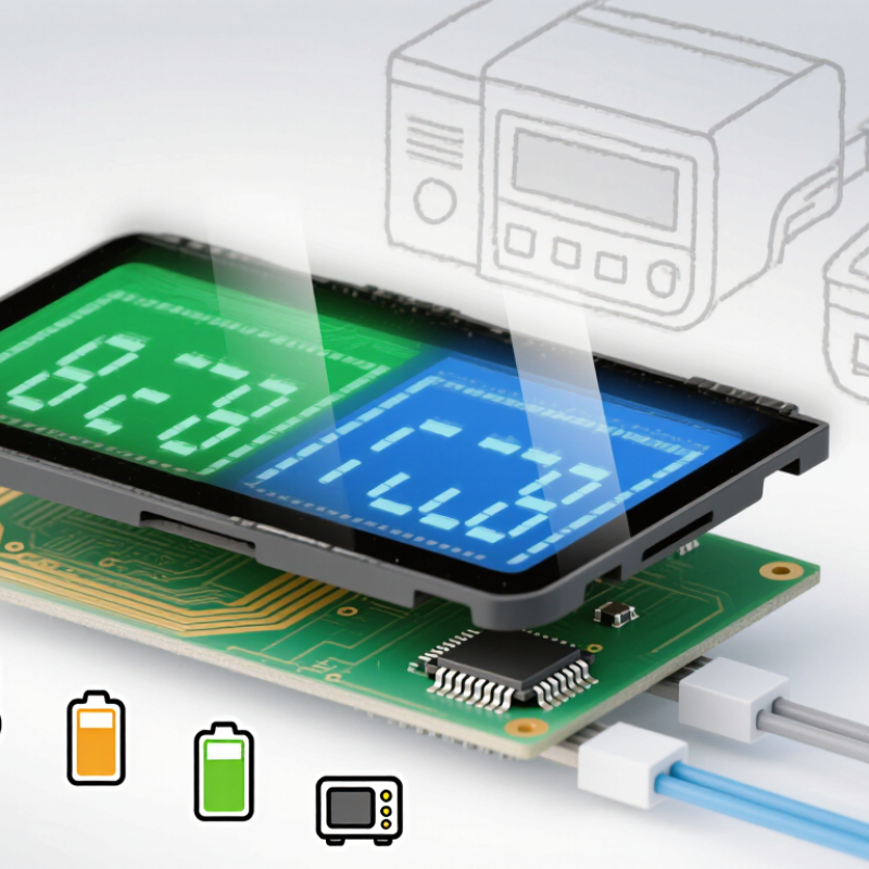
What Is a COB Character LCD?
What Is a COB Character LCD?
A COB character LCD is a small display built using chip-on-board technology. Its controller chip is bonded directly to the circuit board. This design reduces wiring and saves space inside the module. The screen displays fixed characters, such as numbers, letters, and simple symbols. A built-in character generator stores common fonts, allowing a microcontroller to send simple commands instead of drawing every pixel. Many modules use one or two rows, with each row containing several characters. The display may include an LED backlight for dark environments.
In practical equipment, COB character LCDs are valued for clear text, low power use, and straightforward control. Engineers usually check the interface type, operating voltage, viewing angle, and temperature range before installation. Contrast also matters. Poor adjustment can make dark characters appear weak or uneven. The compact layout is useful, but it is not automatically better for every product. During testing, a display can look sharp on a bench and become difficult to read behind tinted plastic. That detail is easy to miss.
Tips: Confirm the character format before ordering. Check the backlight current and controller timing. Test the LCD under real lighting conditions. Allow space for the connector and cable bend. A slightly larger viewing area may improve usability more than a higher contrast rating. Mistakes often happen when only the screen size is compared.
How COB Character LCDs Are Constructed
A COB character LCD is built around a glass display panel and a small printed circuit board. The LCD glass contains transparent electrodes, alignment layers, liquid crystals, and polarizing films. Its character shapes are formed during glass manufacturing, so the panel does not create letters like a modern pixel display. It reveals selected segments instead.
The driver IC is mounted directly onto the circuit board. This is the core meaning of chip-on-board. A bare silicon die is fixed to the board with adhesive, then connected through very fine bonding wires. An epoxy glob covers the die and wires. It protects them from moisture, vibration, and accidental contact. The board also carries the controller interface, resistors, and connection pads. Shorter electrical paths can reduce signal loss and save space.
The glass panel connects to the board through a conductive elastomer strip, often called a zebra connector. Alternating conductive and insulating layers press against matching contacts. A backlight may sit behind the panel, using LEDs, a light guide, and a diffuser. Mechanical pressure matters here. Too little pressure causes missing characters; too much can damage the glass.
In practical inspection, the epoxy seal deserves attention. Small cracks may not cause immediate failure. They can still allow moisture inside later. The construction looks compact, but it is not effortless. Clean bonding surfaces and controlled assembly pressure remain easy to underestimate.
How a COB Character LCD Displays Characters
What Is a COB Character LCD and How Does It Work?
A COB character LCD uses chip-on-board construction to control a liquid crystal display. The driver chip is mounted directly on the circuit board. This reduces wiring and keeps the module compact. In practical testing, the display receives character data through an interface such as parallel or serial communication. A controller then converts each character into a stored dot pattern. That pattern activates selected pixels inside the LCD glass. The result is a readable letter, number, or symbol.
The display does not create light by itself. A backlight, if included, shines through the liquid crystal layer. Each pixel changes how much light passes through. Together, these pixels form familiar characters, often on a fixed grid such as two lines with sixteen positions. The process feels simple, but timing matters. Incorrect initialization can produce blank blocks or scrambled text. I have also found that weak contrast settings make a working display appear defective. That assumption is easy to make, and sometimes wrong.
Tips:
Match the controller settings carefully. Check voltage, contrast, viewing angle, and interface timing before judging the module. Keep signal wires short in noisy equipment. Test with clear characters first. Small errors become obvious quickly. A practical inspection under different lighting is worthwhile, because readability can change more than expected.
Key Components and Their Functions
A COB character LCD is a segmented or dot-matrix display with its driver integrated directly onto the circuit board. “COB” means chip-on-board. This structure removes a separate package and shortens electrical paths. The result is a compact module, often used in meters, controllers, and industrial instruments.
The glass cell contains two transparent electrodes, alignment layers, and liquid-crystal material. When voltage changes, the crystals rotate and control light transmission between two polarizers. The driver IC receives character data, generates multiplexed waveforms, and activates selected pixels. A PCB supplies power and carries the interface. The backlight adds visibility in dark panels. White LEDs are common, but brightness and heat must be balanced carefully.
Small details matter. Poor electrode alignment can create uneven characters. Excessive voltage may accelerate image retention. The COB joint also needs clean soldering and stable temperature control. According to Omdia’s 2024 Small and Medium Display Tracker, display demand is measured across billions of shipped units, with embedded applications remaining significant. The International Data Corporation’s 2024 industrial electronics research also identifies interface reliability and power efficiency as recurring design priorities. These reports do not isolate every COB module, so their figures should not be treated as COB-specific market totals. That limitation matters. A practical test should examine contrast, viewing angle, startup time, and operation from -20°C to 70°C.
Common Applications and Design Considerations
A COB character LCD places its controller directly on the circuit board, then protects it beneath an epoxy coating. This compact structure suits equipment needing simple text, low power, and dependable operation. Typical applications include factory meters, laboratory instruments, vending controls, access panels, and medical equipment. The need remains practical: the International Federation of Robotics reported 541,302 industrial robots installed worldwide in 2023. Many of these systems still require clear local status displays.
Design choices should match the working environment. A 16×2 or 20×4 format may fit a small control panel, but longer messages require scrolling or a larger module. Engineers should check viewing angle, backlight life, contrast, and operating temperature before finalizing the enclosure. In dusty factories, a sealed front window helps protect the display. In bright outdoor areas, transflective designs can improve readability. Electrical noise also matters, especially near motors and relays. A poorly routed ground can create unstable characters. That mistake is easy to miss.
Tips: Use large characters for alarms, test the display at its lowest supply voltage, and validate readability through tinted covers. Allow extra board space around the COB package. Repairs are difficult after epoxy protection, so connector quality and firmware testing deserve attention. The U.S. Department of Energy notes that controls and feedback systems can reduce industrial energy waste, but a display alone cannot deliver those savings. It must present useful information clearly. Some designs still overvalue appearance and underestimate glare.
A COB character LCD uses a controller or driver IC bonded directly to the printed circuit board. The display presents fixed character positions in rows and columns, making it suitable for meters, instruments, control panels, and embedded equipment. The chart shows the total number of character positions for common display formats; these values are calculated from columns multiplied by rows.